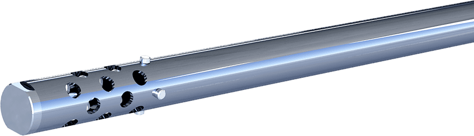
Slug catchers
Designed to protect the check valve and pump from contamination that may be inside the tubing and deposited during installation and operation
Options for applied slug catchers
There are two options for applying a slug catcher:
- installation directly above the check valve of the KOSh type with support on the upper end of a special nozzle. In this case, the lifting limiter of the slug catcher is the lower end of the tubing screwed into the valve coupling;
- installation in any place of the tubing string with support on the upper end of the below tubing. In this case, a drain valve of the KS type shall be screwed into the coupling of the above tubing, which ensures the discharge of liquid from the section of the tubing string located above the slug catcher. Two or more slug catchers can be installed at the request of the customer.
Description of identifiers
The structure of the identifier for a slug catcher manufactured by Almaz Oilfield Service in a separate order, correspondence and other documentation:
- no number
- conventional (serial) version (assembled with bushing)
- 1
- assembled with housing
Components list of slug catchers
| Slug catcher identifier | Outer diameter of the slurry pipe, mm | Length of the slurry pipe, mm | Weight of the slug catcher, kg | Maximum permissible liquid flow rate, m³/day |
|---|---|---|---|---|
| УШ-48/10 | 27 | 1490 | 2,7 | 125 |
| УШ-60/10 | 36 | 1490 | 5,9 | 250 |
| 1УШ-73/01 | 42,2 | 787 | 6,8 | 800 |
| 1УШ-73В/01 | 42,2 | 787 | 6,8 | 800 |
| УШ-73/11 | 42,2 | 1500 | 5,5 | 800 |
| УШ-73/12 | 45 | 1490 | 6,1 | 800 |
| 1УШ-73/31 | 42,2 | 3000 | 13,7 | 800 |
| 1УШ-73/11 | 42,2 | 1500 | 8,8 | 800 |
| УШ-73/31 | 42,2 | 3000 | 10,5 | 800 |
| УШ-73/61 | 42,2 | 6000 | 20,2 | 800 |
| УШ-73/71 | 42,2 | 7000 | 23,5 | 800 |
| УШ-73/72 | 45 | 1490 | 6,1 | 800 |
| УШ-73/92 | 45 | 9870 | 25 | 800 |
| УШ-89/10 | 60 | 1490 | 10,8 | 1250 |
| УШ-89/30 | 60 | 3000 | 21,5 | 1250 |
| 1УШ-89/10 | 60 | 1500 | 15,3 | 1250 |
| 1УШ-89/30 | 60 | 3000 | 25.4 | 1250 |